This manual describes preparation, connection, acquisition, stimulation, event configuration, recording, data management and care of the Inper Air wireless telemetry system. It follows Inper Air User Guide V1.0.1; available channels and settings depend on the delivered implant and installed software. Before use, identify the Air host, implant SN and software version. Implantation and tip placement require the corresponding surgical instructions.
How to use this manual. For a first experiment, follow Chapters 1–4 in order. For a repeat experiment, complete the preparation checks, apply Config and check Trigger separately before recording. If a result is unexpected, use the symptom-based checks in Chapter 6. Click any original illustration to inspect it at its original size.
| Task | Reading route |
|---|---|
| Prepare and connect the system | Chapter 2: workflow, charging, hardware connection and readiness |
| Set up acquisition or stimulation | 3.3 Acquisition and 3.4 Stimulation |
| Coordinate events and timing | 3.6 Marker, 3.7 Output and 3.8 Trigger |
| Record and retain results | 3.9 Preview and recording and 3.10 Data management |
Download the original Inper Air User Guide V1.0.1. Screenshot values and identifiers illustrate the interface; use the settings specified for your experiment.
1 System and interfaces
1.1 Functions and applicable configurations
Inper Air is a wireless telemetry system developed by Inper. It combines computer, wireless communication and sensor technologies for monitoring and control, supporting long-term, continuous physiological recording in naturally awake, unrestrained and freely moving experimental animals. Select an implant and tip configuration that matches the animal model and the intended measurement or stimulation.
Implant designs and tip types accommodate rats, mice, dogs, pigs, monkeys and other experimental models. The implant may be placed subcutaneously or in the abdominal cavity according to the research requirements and corresponding surgical instructions. Tip designs accommodate locations such as the brain, spinal cord, organs and sciatic nerve.
| Function | Examples |
|---|---|
| Biopotential recording | EEG, ECG and EMG. |
| Pressure recording | Arterial and venous pressure. |
| Activity recording | Animal activity and organ activity. |
| Temperature recording | Temperature at the relevant body location. |
| Respiratory recording | Respiratory rate and tidal volume. |
| Closed-loop stimulation | Optogenetic stimulation and bidirectional electrical stimulation channels. |
The functions listed above describe the system family. Confirm the sensors, stimulation tips and channels on the specific implant; one implant does not necessarily provide every listed function. Keep a record linking each animal or sample to the implant SN and the channels used.
1.2 Components, connectors and implant identity
The system comprises an implant, an Air host, a wireless charging board and an Inper One workstation with Air software. The host communicates with the implants; the workstation manages connection, parameters, recording and event functions.
| Host position | Interface or indicator | Purpose |
|---|---|---|
| Front panel | Power | The power indicator lights when the host is powered. |
| Front panel | sDIO | Receives external signals for Trigger. |
| Rear panel | Type-C | Connect the host to the Inper One workstation with the Type-C-to-MCX cable for power and data transmission. |
| Rear panel, eight-antenna host | Antenna | Connect eight external antennas to enhance the signal. |
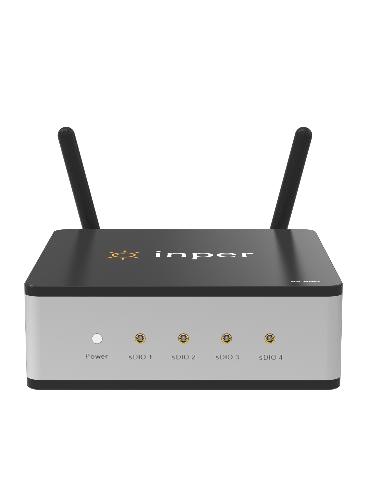
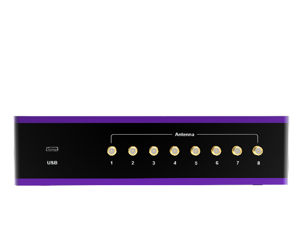
Click a figure to view its original size.
The fully implantable unit comprises a signal-receiving module, sensors, a miniature battery, flexible leads and tips. It communicates with the host in real time, receives commands from the host and sends data to it. Different colors on biopotential acquisition tips identify different tip types; place them at the specified locations according to the surgical instructions.
Optical stimulation wavelengths include 465 nm, 525 nm, 589 nm and 635 nm. The electrical stimulation range is 0 to ±100 μA. Use the wavelength, channel type and range of the delivered implant. Lead length and tip type can be customized; contact Inper support for the required configuration.
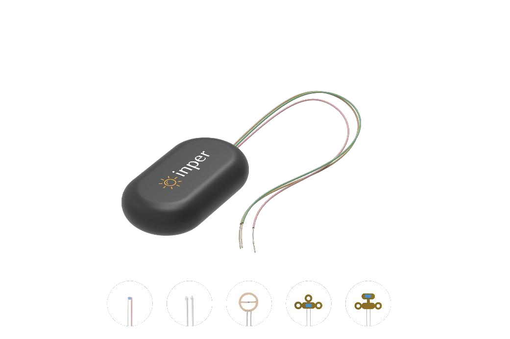
Click a figure to view its original size.
1.3 Communication, charging and event paths
| Path | Role | What to verify |
|---|---|---|
| Implant ↔ Air host ↔ Inper One | The implant exchanges data and commands wirelessly with the host; the host connects to the workstation through the supplied cable. | Host identity, implant connection, battery, signal and channel activation. |
| Power adapter → charging board → implant | The charging board supplies wireless charging and wakes a sleeping implant. | Board power, placement and the battery information in Air. |
| External device → Marker input | Incoming events are marked in the experiment. | Workstation DIO wiring and the enabled Marker item. |
| Output → receiving device | Air sends a TTL event to another device. | Selected output port, duration and the receiving device's response. |
| External input → Trigger | A valid input starts or stops the configured operation. | The applicable input path, start/stop conditions and tested timing. |
Marker records an event, Output sends a signal, and Trigger controls when an operation runs. An event visible on screen does not by itself confirm that an external device received or acted on an output. Charging and software connection also have separate indicators; see 2.2.
2 Experiment preparation
2.1 Complete operating workflow
| Stage | Action | Completion check |
|---|---|---|
| 1 Prepare | Confirm the implant configuration and experimental plan; complete the applicable implantation and recovery procedure. | Animal/sample, implant SN and intended channels are documented. |
| 2 Connect and wake | Connect the host, power the charging board and wake the implant. | The host is powered; the intended implant can be connected in Air. |
| 3 Select and configure | Activate the required channels and set acquisition or stimulation parameters. | Each channel and its units, ranges and timing match the plan. |
| 4 Configure events | Set Marker, Output and Trigger as required. | Required items are added and enabled; inputs and outputs have been checked. |
| 5 Preview | Inspect signals and relevant events before formal recording. | The displayed channel data are plausible; unexplained abnormalities have been resolved. |
| 6 Record | Confirm the file name and tags, then use Start; observe the configured trigger conditions. | Required channels actually run, and their status is checked during the experiment. |
| 7 Finish and retain | Use Stop, find the record in Data, export and verify the copy, then close the software and disconnect the host. | The intended record is present, required results are retained and equipment is shut down. |
Preview data are not saved. Config does not include Trigger. Treat these as separate checkpoints every time you reuse an experiment setup.
2.2 Charging, wake-up and sleep
The charging board transfers energy wirelessly to charge the implant. Charging is supported while the implant is fully implanted subcutaneously or at another appropriate location, including when animal movement changes its relative position and angle.
- Place the charging board on a stable, non-metal surface. Metal surfaces interfere with normal operation. If the table is metal, place a wood board or cardboard box between the table and charging board so that the board is at least 40 cm from the metal surface.
- Connect the supplied power adapter and turn on the switch on the charging board front panel.
- Wait for the screen to display, then place the implant or the animal carrying the implant on the board.
- The board begins charging when it detects the implant. Use the board to wake a sleeping implant before connecting it in software.
- Check the implant battery and signal in Air before starting the experiment.
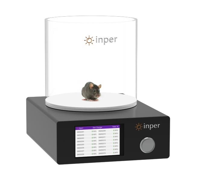
Click a figure to view its original size.
An implant already connected in Air software does not display its information on the charging-board screen when placed above the board, but it remains in the charging state. Check the power, placement and software battery information when assessing charging.
An implant enters sleep after more than ten minutes without connection, reducing battery consumption. A fully charged sleeping implant has approximately six months of standby. Charge stored implants at least every three months to avoid damage from excessive discharge. The implant supports repeated charging; laboratory testing recorded more than 100 stable charge/discharge cycles.
Checking the result. After wake-up, connect the intended implant in Air and read its battery and signal indicators. A lit charging-board screen confirms that the board is powered; it does not by itself establish the implant's remaining charge. Before an experiment, use the manual's recommendation of more than 20% battery and four signal bars. If charging remains doubtful, record the SN, battery readings and board placement before contacting support.
| Situation | Recommended action |
|---|---|
| Implant has been disconnected long enough to sleep | Wake it on the powered board before attempting software connection again. |
| Implant is connected but absent from the charging screen | Check board power, placement and the battery information in Air; this display behavior is described in the original manual. |
| Battery is below 1% | Charge promptly to avoid damage from over-discharge; do not wait for the next scheduled experiment. |
| Long-term storage | Record the last charge date and schedule charging at least once every three months. |
2.3 Hardware connection and identity checks
- Place the workstation, host and charging board on a dry, clean and stable surface. Check the supplied cable, power adapter and implant for visible damage.
- Connect the Air host rear Type-C interface to the Inper One workstation using the supplied Type-C-to-MCX cable. For the eight-antenna host, connect the matching external antennas to the Antenna interfaces shown in Figure 1-1.
- Check the host Power indicator. If it does not light, check the supply and both ends of the cable before attempting software setup.
- Wake the implant on the powered charging board. Log in to the authorized workstation account and compare the host serial number on the Air card with the host intended for this experiment.
- Enter Air, identify the implant by SN and connect its row. If a custom Name is used, compare it with the previously recorded SN/MAC-to-animal mapping.
- Activate only the channels required for the experiment and inspect their status before setting parameters.
Connect external event cables according to their assigned function after checking the input/output definitions on both devices. Do not infer an input's electrical limits from the 5 V Manual Output specification; confirm the receiving device's supported signal.
2.4 Readiness checklist
| Check | Ready to proceed when |
|---|---|
| Animal and implant | Required recovery is complete; implant SN, tip configuration and intended channels match the plan. |
| Power and communication | Host Power is on; the correct host card and implant are selected; the implant status is green. |
| Battery and signal | Battery exceeds 20% and signal is four bars, following the manual's recommendation. |
| Acquisition/stimulation | Required channels are activated; parameters, units, waveform selection and timing have been reviewed. |
| Events and triggers | Required Marker/Output items are enabled and Trigger has been checked separately, including after applying Config. |
| Storage and identity | The intended account, file name, tags and available storage have been checked. |
| Preview check | Signal presentation and relevant events are plausible; unresolved abnormalities have been investigated. |
3 Software operation
3.1 Install Air and enter the device
- Register an account the first time the Inper One workstation is used. Registration is followed by automatic login; on subsequent use, log in to the existing account.
- Confirm that the logged-in account is authorized to use Air, then download Air from Inper Market.
- Find the Air card on the main screen. It shows the connected Air host serial number and the number of implants supported for control.
- Select the card and choose Enter to open the Air main page.
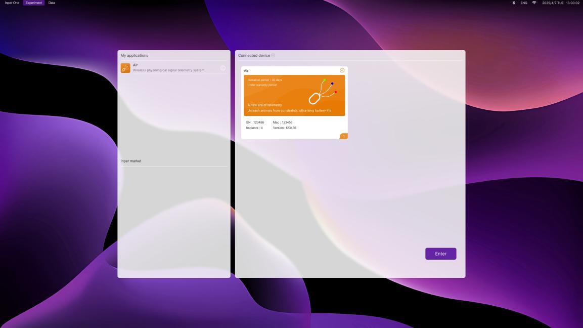
Click a figure to view its original size.
Completion check. After Enter, the Air main page should be available for selecting implants. If Air is unavailable in Inper Market, first check the current account and its Air authorization. If the host card is missing or its serial number is unexpected, return to the connection checks in 2.3. Account authorization, host recognition and implant connection are three separate checks.
3.2 Main page, implants and signal display
The main page contains the implant list, channel data display and controls for configuration and experiment operation. Check the implant identity and state before changing its channel parameters.
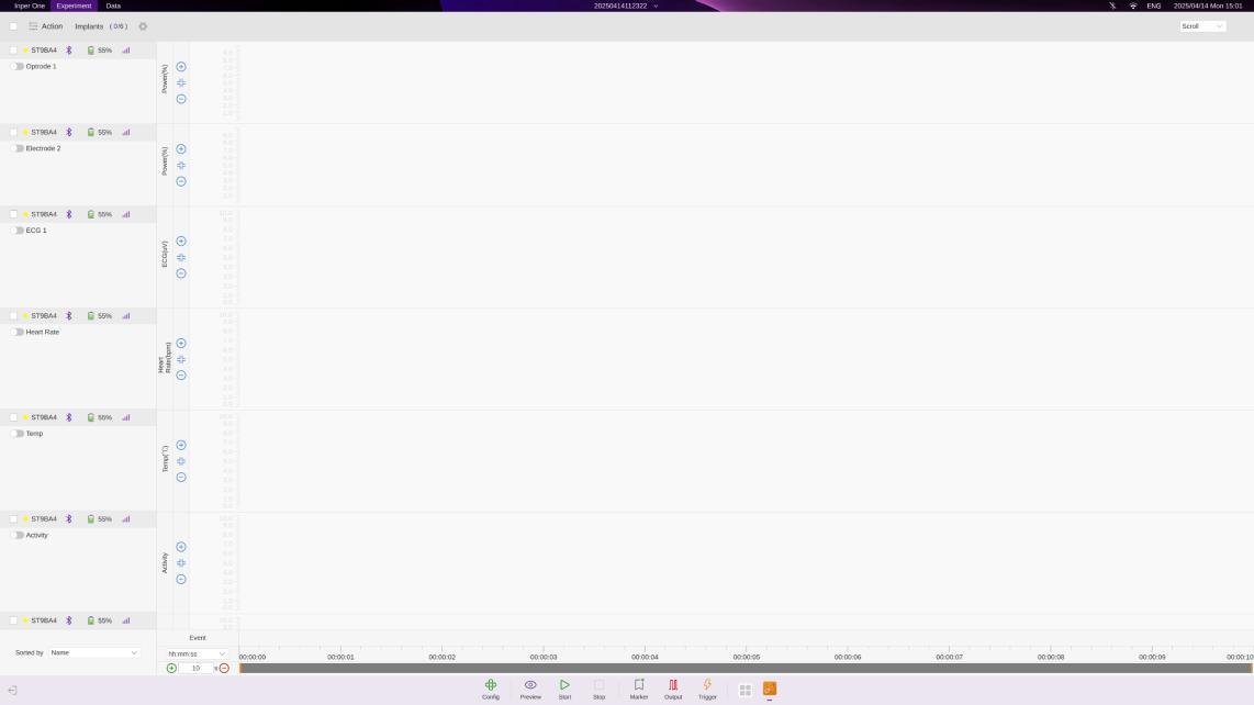
Click a figure to view its original size.
Implant list and channel activation
| Item | Operation or meaning |
|---|---|
| Yellow state | The implant is waiting to connect. Use the connection action on the right of that implant row. |
| Green state | The implant is connected and its state is normal. |
| Red state | The signal is abnormal; check connection and signal conditions before continuing. |
| Battery and signal | Displayed in real time. Battery above 20% and signal strength of four bars are recommended before beginning. |
| Channel activation | One implant may contain multiple channels. Activate the required channels, then set their parameters before the experiment. |
Open the implant parameter dialog with the parameter-settings action for that implant, or double-click its row in the implant list. Name initially shows the factory-configured SN. Double-click the name-edit control to rename the implant. The dialog also shows the MAC address and current version.
Batch operations
Select multiple Implant entries and use the batch-operation control. Available operations are batch connect, batch disconnect, batch activate and batch deactivate. Check the selected implants before applying the operation.
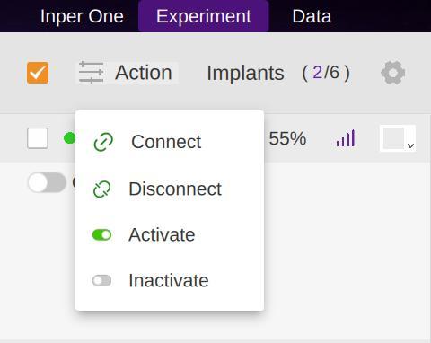
Click a figure to view its original size.
Page display and adjustment
Use the color-change control for the current implant. All channels under that implant are displayed in the same selected color.
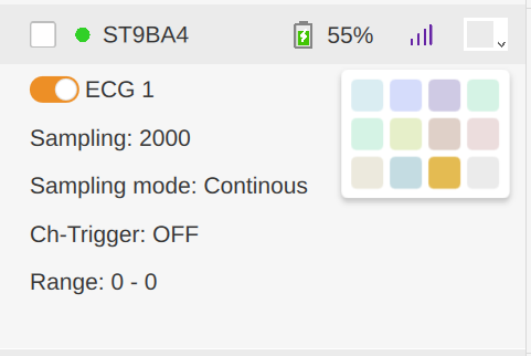
Click a figure to view its original size.
| Control | Display behavior |
|---|---|
| Page | Data is displayed in pages covering a time interval. When one page is filled, the display switches to the next page and the new data replaces the previous page on screen. |
| Scroll Mode | New data is added on the right. Older data moves left until it leaves the display area. |
| Sort | Sort by implant name or sensor type. |
| Event | Shows Marker and Output events at their corresponding times when those functions are configured. |
| Time axis | Use the time-axis dropdown to choose seconds, days or milliseconds. |
| Time window | In Scroll mode, enter a value for the visible time-window length or drag the left and right control points. Double-click to release and return to the latest data page. |
Recommended display check. First verify the implant identity, then the connection state, then the active channels. With several implants, assign distinguishable colors and choose a consistent sort order. Finally set the time-axis unit and viewing window so the relevant changes are readable. These are display controls: scrolling old data out of view is not a command to delete a saved record.
When comparing channels, check the selected sensor, displayed unit and time window before interpreting differences. If the display appears to stop updating, check whether the viewing window has been moved away from the latest data; in Scroll mode, double-click to return to the latest page. Then inspect connection and trigger state if updates are still absent.
3.3 Acquisition parameters and signal checks
| Parameter | Setting and effect |
|---|---|
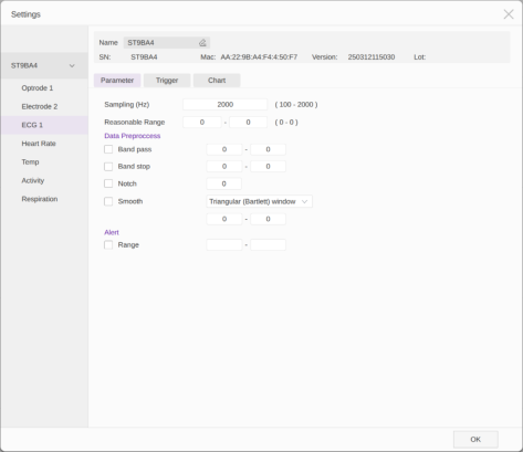
| Sampling | ECG: 100 Hz–2 kHz; temperature: 1 Hz; activity: 1–10 Hz. Select the sampling setting for the actual acquisition channel. |
| Reasonable Range | Values within the entered range are treated as valid; values outside it are treated as unreasonable. |
| Data Preprocess | Real-time band-pass, band-stop and notch filtering, plus Smooth for data smoothing. |
| Alert | Set a warning range. Values outside it are displayed as red points on the acquisition page for observation. |
Set ranges and processing for the quantity and units of the selected channel. Check the resulting data in Preview before formal recording.
Parameter setup sequence
- Open the settings for the intended implant and select the acquisition channel. Confirm the channel type and the unit displayed.
- Set Sampling within the range offered for that channel. The ECG, temperature and activity ranges above apply to the V1.0.1 instructions; do not transfer one channel's range to another sensor.
- Set Reasonable Range according to the expected measurement range. Check that its lower and upper bounds are ordered correctly and use the channel's unit.
- Select Data Preprocess only where needed for the experiment. Review each enabled filter or smoothing setting; a smoother display alone does not prove a better measurement.
- Set Alert to the observation limits required by the experiment. Review the relationship between those limits and Reasonable Range.
- Return to Preview and check the displayed baseline, variation, abnormal points and connection state. If you change a parameter, repeat this check before recording.
| Setting | Question it answers | Interpretation |
|---|---|---|
| Sampling | How often is the channel sampled? | Use a value supported by that channel and appropriate to the experiment. |
| Reasonable Range | Which values are treated as reasonable? | It defines the validity range described by the software. |
| Alert | Which values require attention? | Out-of-range points appear red and can be used by an Alert event condition. |
| Data Preprocess | What real-time processing is applied? | Record the selected processing when comparing experiments. |
Do not assume that Reasonable Range deletes out-of-range samples, or that Alert automatically stops recording. The V1.0.1 instructions do not define those behaviors. Inspect unexpected values together with signal quality and experimental context before changing limits.
3.4 Waveform, Sweep and stimulation timing
Use the add-Waveform action to create a waveform. Optical stimulation supports Square, Constant, Sine, Triangular, Linear, Exponential and Polynomial. Electrical stimulation supports Square and Constant. Enter parameter values using the units and ranges shown for the selected channel.
| Waveform | Parameters |
|---|---|
| Square | Pulse width, frequency, power range and output time. |
| Constant | Power and output time. |
| Sine | Frequency, power range and output time. |
| Triangular | Pulse width (the time from Low power to High power), frequency, power range and output time. |
| Linear | Power range and output time. |
| Exponential | Power and output time. The minimum power must not be zero. |
| Polynomial | Power and output time. |
- Add and configure the required Waveform items. They appear in the waveform table.
- To change an item, select it and right-click to edit its parameters or delete it. A Waveform selected in a Sweep cannot be deleted directly; first remove its selection in the Sweep.
- Use the add-Sweep action, select the required waveforms and add them to the Sweep item. One Sweep item contains up to eight Waveform items.
- Set Duration for the experiment. The selected Waveform items cycle within the configured Sweep-Duration time.
- Enable Timer (labelled Time in the illustrated window) when the program should run for a set duration. Do not use Timer when optical/electrical stimulation is triggered by external signals in Real Time or Gate mode.
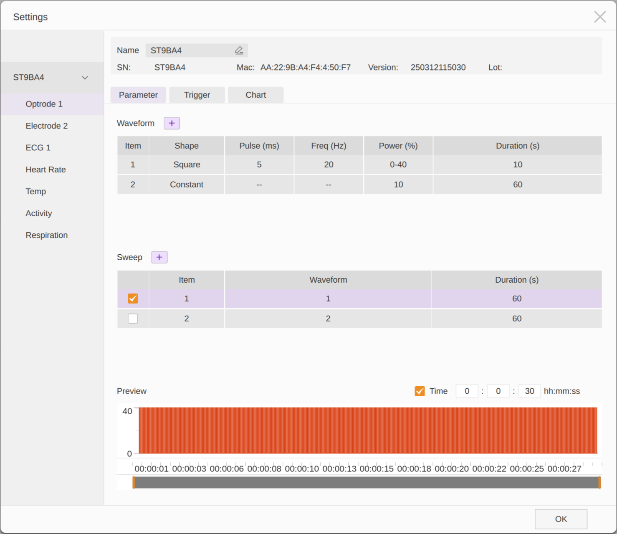
Click a figure to view its original size.
Understand the three levels before setting values. Waveform defines an individual waveform and its parameters. Sweep selects the Waveform items to run and defines the duration in which those selected items cycle. Timer controls operation for a set duration when enabled; Trigger defines the start and stop conditions. Review these together rather than treating all duration fields as the same setting.
| Review item | What to check |
|---|---|
| Implant and channel | Confirm optical or electrical stimulation and the delivered tip configuration. Available waveform types differ. |
| Amplitude and unit | Use the unit and allowed range displayed for that channel; do not copy optical power values directly into an electrical channel. |
| Waveform parameters | Review every field exposed by the selected type, including pulse width, frequency, low/high values and duration where applicable. |
| Waveform-to-Sweep selection | Confirm which items are included; a saved Waveform still has to be selected in the intended Sweep. |
| Sweep duration | Review the intended cycling time and the selected items; a Sweep can contain at most eight items. |
| Timer and Trigger | Check the stopping condition separately. Do not use Timer with external Real Time or Gate stimulation. |
Editing an existing setup. Review the Sweep selection after changing a Waveform. To delete a referenced Waveform, first remove its selection from the Sweep, then delete it through the Waveform table's context menu. Reopen the settings to verify the intended combination before saving Config. Record the final waveform parameters and Trigger settings with the experiment.
3.5 Save and reuse Config
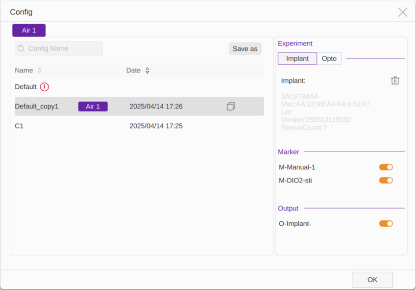
Choose Config at the bottom of the main page to open the configuration window. Initially only Default is available. Select a configuration in the list to inspect its right-hand details: the implants and acquisition/stimulation parameters, Marker settings and Output settings.
- Save: after setting the experiment parameters, choose Save as and enter a configuration name to create a new configuration.
- Apply: select the required configuration, review its details and use the apply action. An Air label appears on that row after successful application.
- Delete: select the configuration and use its delete action. Deletion is irreversible; check the selected name before proceeding.
- Rename: double-click the configuration name, enter the new name and press Enter.
- Activate Marker and Output: use the corresponding switches to enable the items needed for the current experiment.
- Save on exit: if Config has not been saved when exiting, enter a Config name in the dialog and choose Yes.
Config is stored only under the corresponding account on the current workstation. A different workstation or account requires the parameters to be configured again. Config excludes Trigger settings: check Trigger separately before each experiment, including after applying an existing configuration.
Click a figure to view its original size.
Reusing a configuration
- Check that you are using the intended workstation and account. Open Config and select the saved configuration.
- Review the right-hand details before applying it: implant identity, channel parameters, Marker and Output must match this experiment.
- Apply the configuration and confirm that the Air label appears on its row.
- Return to the main page to check the active channels and parameters. Open Marker and Output to review the items that should be enabled.
- Open Trigger separately and check start, stop, delay, scheduled time and repeat values as applicable. Complete Preview before formal recording.
Suggested naming practice. Use a configuration name that identifies the protocol and revision, and distinguish a verified configuration from a trial setup. After changing experimental parameters, use Save as to retain a separately named configuration when you need both versions. A saved Config is a parameter preset, not a copy of the recorded data or a complete record of Trigger settings.
3.6 Marker: mark experimental events
Marker adds time markers to the experiment. Choose DIO, Manual or Implant as the source.
| Source | Setup |
|---|---|
| DIO | Connect an external device to a workstation DIO interface with an MCX cable. Its input signal is used as a Marker. The workstation provides 32 DIO interfaces. |
| Manual | Set Hotkey to a letter or number. Each press adds one Marker. |
| Implant: stimulation | Choose Start, Stop or Start & Stop. |
| Implant: acquisition | Choose Start, Stop, Start & Stop, Alert, Value or Change Rate. Alert means outside the warning range; Value means outside the specified data range; Change Rate means the rate of change exceeds the set value. |
- Choose the source and configure its input, Hotkey or implant/channel condition.
- Use the add action to put the Marker in the list on the right.
- Turn on the configuration switch so that the item is used during the experiment.
- To remove a Marker, select the item and use the remove action.
- Choose OK to close the dialog. Check Marker events in the Event area on the main page.
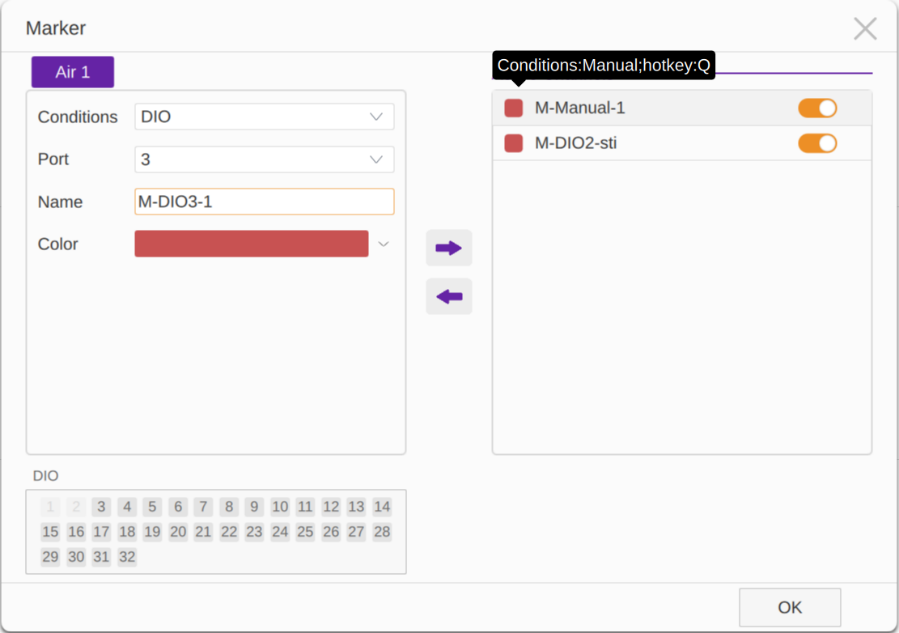
Click a figure to view its original size.
Choosing a source. Use Manual for an event that the operator identifies, DIO for an event supplied by external equipment, and Implant for an event defined by a specific implant/channel. For Implant, check both the channel and the condition; Start & Stop requests both event types, while Alert, Value and Change Rate refer to different criteria.
Verification sequence. Confirm the item is present in the right-hand list and its switch is on. During a controlled check, generate one identifiable event through the chosen source and inspect Event at the corresponding time. If it is absent, check the source, channel or Hotkey and any DIO wiring before changing threshold values. For a threshold condition, first check that the displayed channel value actually meets that condition. Repeated markers should be investigated against the signal and condition; the manual does not specify debounce or a minimum event interval.
3.7 Output: signal output and closed-loop connection
Output sends signals to mark events or trigger other devices. Use MCX cables to connect the receiving device to a workstation DIO interface for TTL output. The workstation has 32 DIO interfaces. Check the receiving device input instructions and signal compatibility before connection.
| Setting | Behavior |
|---|---|
| Manual | Hotkey can be a letter or number. Each press outputs one 5 V signal. |
| Implant: stimulation | Output on Start, Stop or Start & Stop. |
| Implant: acquisition | Output on Start, Stop, Start & Stop, Alert, Value or Change Rate; the condition meanings match the corresponding Marker options. |
| More Setting | Set the output duration within 2–9999 ms. |
- Select Manual or Implant and configure the Hotkey or implant/channel event condition.
- Select the intended output path and set the output duration in More Settings.
- Use the add action to place the Output in the right-hand list, then turn on its configuration switch.
- To remove an Output, select the item and use the remove action. Choose OK to close the dialog.
- Check the Output events in the Event area and separately verify the receiving device response before formal use.
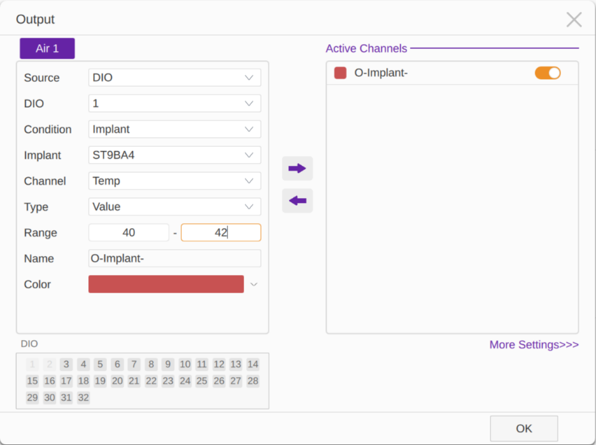
Click a figure to view its original size.
Closed-loop example: a heart rate above 300 bpm causes an output on workstation DIO1. An MCX cable links workstation DIO1 to DIO2; an optical stimulation channel is set to receive the DIO2 trigger, with Edge mode and 10 s given as the example. Each occurrence of the set condition then initiates the configured stimulation in that example.
The 300 bpm threshold and 10 s duration are demonstration values, not recommended experiment settings. Set thresholds and stimulation parameters for the actual experimental design and implant. Edge is named in this example, while the Trigger section lists Realtime and Gate for external modes. Confirm the receiving path, available mode and start/stop behavior for the actual software/hardware version before reproducing the example.
Output verification has two parts. First check that Air registers the expected output event in Event. Then check the receiving equipment for the corresponding input or action. If the first part succeeds and the second does not, inspect the selected output port, cable, receiving input, signal compatibility and output duration. Do not treat an Event entry as proof of delivered stimulation.
Closed-loop commissioning order. Verify acquisition first, then the condition used to generate Output, then the connection to the receiving input, and finally the stimulation channel's Trigger and stopping condition. Test one link at a time so that an unexpected response can be traced to the source condition, signal path or receiving operation. Use the worked procedure in 4.3 before combining all links in an experiment.
3.8 Trigger: start, stop and timing
For an individual implant channel, choose Set Channel Trigger, or double-click the implant row and open Trigger in its dialog. Confirm the selected implant and channel, then set its start and stop conditions.
| Option | Behavior |
|---|---|
| Immediately | The program starts or ends immediately when Start or Stop is clicked. |
| Delay (s) | After Start is clicked, the program begins after the configured delay. |
| At time | Starts at the configured time in the 24-hour clock. A time earlier than the current time is interpreted as the next day. |
| Repeat | Sets the number of complete start-to-stop cycles to repeat. For example, 10:00 start, 12:00 stop and Repeat 7 runs daily from 10:00 to 12:00 over the next seven days. |
| After Start | Stops after running for the configured duration. |
| Exterior | Receives external-device signals to trigger running or stopping. When both Start and Stop are Exterior, Mode provides Realtime and Gate. |
For external triggering, the host front-panel sDIO is the external-signal input identified in the hardware section. The closed-loop example uses a workstation DIO receiving path. Use the receiving path applicable to the actual configuration and check the connected device interface instructions.
Realtime is described in V1.0.1 as triggering on an input falling edge, and Gate on the next rising edge. This wording does not fully specify the start/stop mapping or duration for each mode. Check those behaviors against the actual version instructions and verify them with a test signal; do not infer a complete timing sequence from the edge wording alone. For external Real Time or Gate stimulation, do not enable Timer.
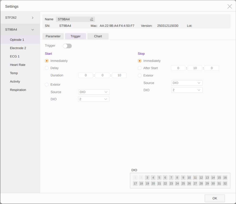
Click a figure to view its original size.
After configuring Trigger, check Start, Stop, timing values and Repeat wherever applicable. Check Trigger again after applying Config because it is not stored in Config.
Trigger setup sequence
- Identify the implant and channel whose start/stop behavior you are changing.
- Select the start condition. For a delay or scheduled time, check the displayed unit and the workstation's current date/time before entering a value.
- Select the stop condition separately. If After Start is used, check the operating duration; if scheduled start and stop are used, check both times.
- When Repeat is available and required, review the entire start-to-stop cycle and the intended number of repetitions.
- For Exterior, confirm the actual input path and available mode for this hardware/software version, and verify both start and stop with a suitable test signal.
- Recheck Timer on a stimulation channel. External Real Time/Gate stimulation must not also use Timer.
Start initiates the configured experiment behavior. With Delay, At time or an external condition, a channel may be waiting rather than running immediately. Check the condition and actual channel response before interpreting a lack of immediate data or stimulation as a fault. For scheduled experiments, record the planned start date as well as the time to avoid a next-day scheduling error.
3.9 Preview, formal recording and shutdown
| Operation | Purpose | Required check |
|---|---|---|
| Preview | Inspect data and experimental behavior before formal recording. | Preview data are not saved. Check selected channels, signal quality and relevant events. |
| Start | Begin the formal experiment according to Trigger settings. | Confirm the file name first, then check whether required channels have started or are waiting for their conditions. |
| Stop | End the current experiment. | Check that the intended operation has ended and locate the completed record in Data. |
Before Start
- Complete the readiness checklist in 2.4. If a Config was applied, recheck Trigger separately.
- Set the file name and Tag as described in 3.10.
- Use Preview to inspect each required channel. Look for plausible values and trends, unexpected alert points, abnormal connection state and expected Marker/Output events.
- If stimulation or external equipment is involved, verify the setup and the installed version's output behavior before testing. Do not assume that a preview is an isolated simulation.
- After resolving unexpected behavior, use Start for the record you intend to retain.
During recording. Monitor battery, signal, channel data and Event. Record the time and circumstances of an abnormality in the experiment notes. Check a delayed or externally triggered channel against its configured condition. Investigate an unexplained red status or missing response before relying on the affected interval.
Finish in this order
- Use Stop and verify that the intended experiment has ended. Check any independently operating external equipment separately.
- Open Data in the same account and verify the completed record's name and time. Export and check the results that must be retained.
- Save the required Config and record Trigger settings separately.
- Close the software before disconnecting the Air host. There is no need to disconnect implants one by one in the software; without a host connection, they enter sleep after approximately ten minutes as described in the manual.
- Turn off equipment and disconnect power after use. Check the implant charge and arrange recharging or storage maintenance as needed.
3.10 File naming, Data and export
File naming and Tag
- Before choosing Start, select the file name at the top of the acquisition page and enter a recognizable name for the upcoming recording.
- Add a Tag when classification is needed. A record may have multiple tags; select an existing tag offered by the field or enter a new one and use Add Tag to add it to the list. Remove an unwanted tag with its delete control.
- Confirm the entry using OK when provided, then reopen the window to check the file name and tags before starting the experiment.
- After Stop, find the completed record in Data. The name at the top of the acquisition page is prepared for the next recording.
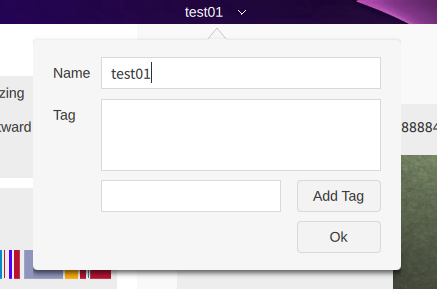
Click a figure to view its original size.
Find and check a record
- Open Data while logged in to the account used for the experiment.
- Search or filter by File name or Tag to locate the intended records. Use the Start/Stop Time columns to distinguish experiments with similar names.
- Check the file name, tags, recording time and device information. Select the completed record or records required for export.
Export data
- Connect a USB drive or external hard drive with enough free space, then open Data.
- Select the intended completed records. Before using a list-wide selection box, check which records are included in the current view.
- Choose the export action. In the export window provided by the installed version, select the destination drive and folder, then confirm with Export or OK, as shown by that version.
- Wait until export is complete. Check the destination folder and the exported files before disconnecting the drive or deleting the workstation records.
Delete data
- Locate and select only the records intended for removal. Check that any required exported copy is available.
- Choose the delete action and review the selected records again in the confirmation dialog.
- Confirm permanent deletion only when the selection is correct; choose Cancel to keep the records.
Do not export or delete a record while acquisition is running. End the experiment with Stop before managing that record. File-management controls may vary by workstation version; use the controls shown in the installed version.
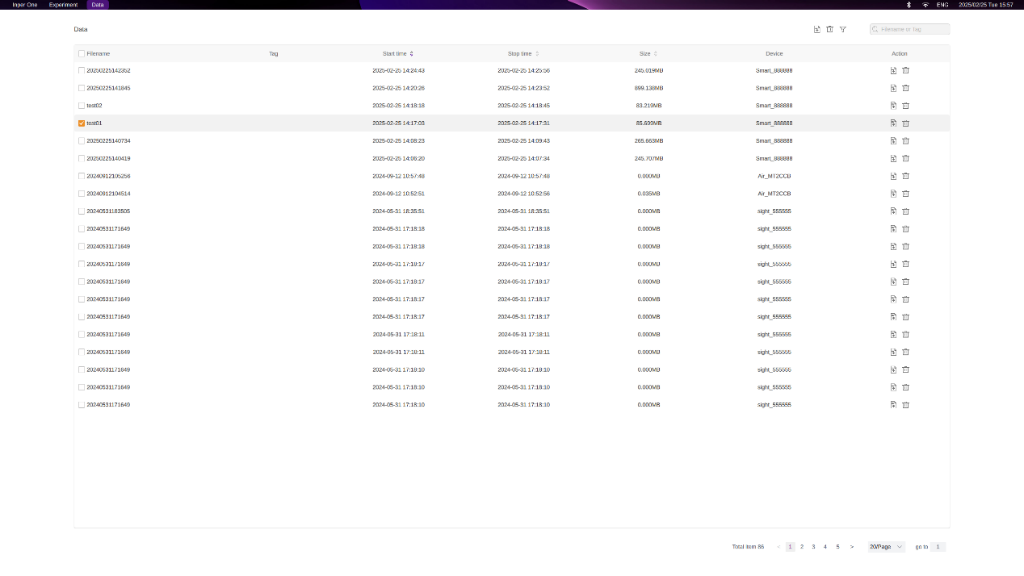
Click a figure to view its original size.
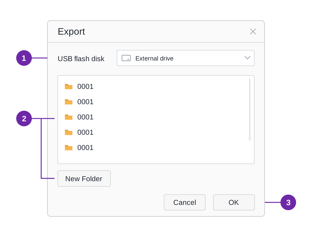
1 Select the destination drive. 2 Select a folder or use New Folder. 3 Confirm the destination. This schematic follows the interactive prototype; the installed version may label the confirmation button OK or Export. Drive and folder names are examples.
Suggested record naming. Use a consistent pattern such as date, animal/sample ID, protocol and run number. For example, 20261012_M01_ECG_R01 is an organizational example, not a required software format. Use Tag for stable categories such as protocol or group, and keep the animal-to-SN mapping in the experiment log. Check that the installed version accepts the entered name.
Verify an export before removing the source
- Compare the selected record list with the intended experiment; check similar names against start/stop time and device information.
- Confirm the destination drive and folder in the export window. Create a folder with New Folder when needed.
- Wait for the export operation to finish. If an error is shown or completion is unclear, retain the workstation record and investigate the drive, available space and destination.
- Inspect the destination folder for the expected exported items. Where the applicable analysis software is available, open the intended record to verify that the file is readable and corresponds to the experiment.
- Only after the required copy has been checked should you remove the drive or consider deleting the workstation record.
When exporting several records, check each intended record rather than relying only on a single completion message. Before deletion, review the selection again after changing a search or filter. Cancel the deletion if the selected records or backup status are uncertain.
4 Worked operating procedures
The following procedures illustrate the sequence of operations. Choose the actual sampling, thresholds and stimulation values from the experiment protocol and the delivered implant configuration.
4.1 Basic physiological recording
- Complete charging, host connection and implant identity checks. Select the intended acquisition channel and activate it.
- Set Sampling, Reasonable Range, Data Preprocess and Alert as described in 3.3. Leave event functions that are not required for this procedure disabled.
- For a manually started and stopped trial, select the corresponding Immediately conditions in Trigger. Check the intended channel again.
- Set a recognizable file name and appropriate tags. Use Preview to inspect the signal, connection state and any alert points.
- Use Start, observe the required channel, and use Stop at the end of the planned trial.
- In Data, locate the completed record by name and time. Export it, check the destination and retain the experiment's parameter notes.
Completion criteria: the intended channel ran, the corresponding completed record is found, the exported copy is checked, and the implant identity and parameter settings remain traceable.
4.2 Recording with a manual event marker
- Prepare the acquisition procedure in 4.1 and open Marker.
- Select Manual, assign a letter or digit to Hotkey, add the item to the list and enable its switch.
- Generate one identifiable test event and confirm its appearance in Event. Confirm what the event represents in the experiment notes.
- Begin formal recording. When the designated experimental event occurs, press the assigned key once and check the corresponding marker.
- Stop, locate the completed record and export it. Retain the marker meaning and any observations needed to interpret the event times.
A manual marker records the operator's action. When interpreting timing, distinguish that action from an event generated directly by external equipment or by an implant condition.
4.3 Check an externally triggered or closed-loop setup
| Step | Check independently | Evidence to retain |
|---|---|---|
| 1 Acquisition | The intended channel is connected and its values are plausible. | Implant SN, channel and acquisition settings. |
| 2 Event condition | The chosen Alert, Value or Change Rate condition matches the intended event. | Condition, unit, threshold and the observed qualifying event. |
| 3 Output | The item is enabled; the output port and duration match the connection plan. | Output settings and the corresponding Event observation. |
| 4 Signal path | The cable connects the specified output to the applicable receiving input. | Port-to-port connection and receiving-device response. |
| 5 Stimulation | The intended implant, channel, Waveform/Sweep, Trigger and stop behavior are verified. | Final stimulation settings and the tested start/stop response. |
| 6 Combined trial | The complete chain responds as intended before the formal experiment. | File name, test result and any deviations requiring correction. |
For the original manual's DIO1-to-DIO2 example, verify that the installed version supports the stated receiving path and Edge mode before using its 300 bpm/10 s demonstration. If the offered modes or input paths differ, obtain the matching version instructions from support. Do not substitute a mode based only on a similar name.
5 Precautions, care and maintenance
5.1 Handling and operating precautions
- Operate according to the product user instructions.
- Place the instrument on a dry, clean and stable surface, away from direct sunlight.
- Keep the instrument away from flammable or explosive materials.
- Do not spill any liquid on the instrument.
- Connect the power adapter to a socket or power strip that meets the applicable national standards.
- Protect the implant shape and its flexible tips during surgery. Pulling can damage them.
- Avoid excessively low implant charge. Charge promptly below 1% battery, as excessive discharge may cause irreversible battery damage.
- Use the power adapters and accessories supplied by Inper.
- Avoid impacts to the instrument.
- Switch off the equipment and disconnect power after the experiment.
- Contact Inper technical support if any issue arises during use.
5.2 Reuse and storage
For reuse, remove the implant carefully from the animal and protect the flexible leads and tips. The V1.0.1 reuse instructions specify disinfection with 75% alcohol, followed by an outside-the-body connection and light-output check before reimplantation. This is not a complete surgical or disinfection procedure: follow the corresponding surgical operating instructions for the full preparation and implantation steps.
- Complete removal and cleaning/disinfection preparation according to the applicable operating procedure.
- Check the implant connection outside the body; if an optical stimulation channel is present, check its light output.
- If damage, abnormal connection or abnormal light output is found, stop the reuse process and contact technical support.
- Only continue with the corresponding implantation procedure after the required checks are normal, handling the implant carefully throughout.
- If storing the implant unused, charge it at least every three months to avoid excessive discharge.
Suggested maintenance record. Record the implant SN, last use, charging dates, observed damage or abnormal behavior, and the result of the pre-reuse connection/light-output check where applicable. When taking an implant out of storage, check its condition, charge and wake it, and verify connection before returning it to an experiment.
5.3 Warranty and service
The terms listed in V1.0.1 specify a three-year warranty for the Air host and charging board, with no free repair or maintenance after the warranty period. The manual does not state this three-year period for implants. Actual service coverage is subject to the purchase and after-sales records.
The listed circumstances in which Inper does not take responsibility for instrument reliability and safety are:
- Disassembly by personnel not authorized by Inper.
- Readjustment by personnel not authorized by Inper.
- Modification by personnel not authorized by Inper.
- Repair by personnel not authorized by Inper.
- Human-caused damage, including high temperature, water ingress, connection to electrical equipment that does not meet national standards, or severe impact.
- Use contrary to the user instructions.
The conditions described for Inper responsibility during the warranty period are:
- All assembly, disassembly, repair, adjustment and upgrade work is performed by Inper professionals.
- Connected electrical equipment meets national standards.
- The instrument is used correctly according to the user instructions.
6 Troubleshooting
6.1 Troubleshooting order and pre-experiment review
Work from the physical connection toward software settings: power and cables → implant wake-up and connection → channel activation → parameters and Trigger → event configuration → file selection and export. Change one relevant item at a time and repeat the same check. Use the readiness checklist in 2.4 before restarting an experiment. If an abnormality persists, retain the current settings, error text and relevant screenshots for support.
6.2 Connected implant missing from the charging screen
An implant already connected in Air remains in the charging state above the board even though its information is not displayed there. Check board power, non-metal placement and the battery information in Air; a missing screen entry alone is not the indication of charging failure.
6.3 Implant connection or channel display is abnormal
Check that the host is powered and connected to the workstation, the implant has been awakened on the charging board, and the intended implant row has been connected. Check the status color, battery and signal, then confirm that the required channel is activated. If the abnormal state remains, provide these details to support.
6.4 Config is missing or Trigger differs
Config belongs to the corresponding account on the current workstation. A workstation or account change requires parameters to be configured again. Trigger is excluded from Config and must be checked separately even when the other saved parameters have been applied.
6.5 Marker or Output has no expected event
Confirm that the item was added to the right-hand list and enabled. Check its source, Hotkey or implant/channel condition and relevant DIO connection. For Output, check the receiving device response separately from the Event display.
6.6 No saved record after Preview
Preview does not save data. Set the file name before acquisition and choose Start for a formal experiment, then use Data to select and export the resulting recording.
6.7 A Waveform cannot be deleted
A Waveform selected in a Sweep cannot be deleted directly. Remove its selection in the Sweep first, then select the Waveform item and use the right-click delete action.
6.8 Scheduled start is on the next day
At time uses the 24-hour clock. A start time earlier than the current time is treated as the next day; review the start and stop times together with Repeat before starting.
6.9 Symptom-based diagnostic table
| Symptom | Checks in order | Expected outcome / next action |
|---|---|---|
| Host not recognized | Power indicator → cable ends → Air card serial number → account and authorization. | The intended host card is available. If not, provide the host SN and connection details to support. |
| Implant cannot connect or is red | Wake-up → correct implant row → battery → signal → host connection. | The intended implant connects normally. If red persists, record the state and signal before seeking support. |
| Connected but no expected trace | Channel activation → selected channel → Trigger waiting condition → display time window. | The intended channel runs when its condition is met and the latest data can be viewed. |
| Unexpected red points | Displayed value and unit → Alert bounds → signal quality and experimental event. | Determine whether the alert reflects the configured limit or an unexplained signal problem; do not dismiss it by widening limits alone. |
| Output event visible, receiver does not respond | Selected output → cable → receiving input → compatible signal and duration → receiving-device configuration. | Verify the receiver separately; retain both the Event observation and its response. |
| Record cannot be found | Was Start used? → was the experiment stopped? → same account → File/Tag filter → start/stop time. | Locate the completed record. Preview-only data cannot be recovered as a saved experiment. |
| Export drive missing or export incomplete | External drive connection → destination selection → available space → error/completion message. | Keep the original record until the expected files are checked in the target folder. |
| Export/delete unavailable for a record | Check whether recording is still in progress; use Stop before managing the completed record. | Return to Data and select the completed record again. Do not interrupt acquisition by disconnecting the host. |
7 Terms and parameter reference
| Term | Meaning |
|---|---|
| Output | An output or output port that sends a signal to another instrument for marking or triggering. |
| Trigger | A trigger input or condition that initiates an operation when a valid signal is received, for example starting an optical/electrical stimulation tip. |
| High level | A logic 1 state. A receiving device may recognize it as on/active or use it to trigger an operation, according to its configuration. |
| Marker | A time marker for an experiment event, from DIO input, a Hotkey or an implant event/condition. |
| DIO / sDIO | Workstation DIO is used for Marker input and Output; host sDIO is identified as an external Trigger input. Use the applicable receiving path for the actual configuration. |
| Config | A parameter configuration saved in the current workstation account. It includes Marker and Output, but excludes Trigger. |
| Term / parameter | Meaning or V1.0.1 value |
|---|---|
| SN / Name / MAC | SN identifies the implant; Name initially displays SN and can be renamed; MAC is shown in implant information. Retain the identity mapping when renaming. |
| Waveform / Sweep | Individual waveform settings / selected waveform combination and cycling duration; at most eight Waveform items per Sweep. |
| Battery before an experiment | More than 20% recommended; charge promptly below 1%. |
| Signal before an experiment | Four bars recommended. |
| Sleep / storage charging | Sleep after approximately ten minutes without connection; charge at least every three months during storage. |
| ECG / temperature / activity sampling | 100 Hz–2 kHz / 1 Hz / 1–10 Hz, respectively. |
| Manual Output / output duration | 5 V / 2–9999 ms in More Settings. |
| Workstation DIO | 32 interfaces described for Marker and Output. |
This reference summarizes the V1.0.1 instructions and does not replace channel-specific settings or the receiving equipment's interface specifications.
8 Technical support
Contact Inper for technical problems with its products and services, configuration questions or the corresponding surgical and Inper One operating instructions.
| Contact | Details |
|---|---|
| Telephone | 0571-86035376 |
| support@inper.com | |
| Website | https://www.inper.com/ |
| Address | 12th floor, Building 12, 669 Cangxing Street, Cangqian Subdistrict, Yuhang District, Hangzhou, Zhejiang, China. |
Prepare the Air host serial number, implant SN, software version, intended operation, steps preceding the problem, error text and relevant screenshots. For a service assessment, also provide the purchase and after-sales records.
| Information | What to provide |
|---|---|
| Device identity | Host SN, implant SN/Name/MAC where shown, and the affected channel or tip type. |
| Software and setup | Installed version, current Config name, Trigger settings and relevant Marker/Output items. |
| Observed problem | Expected result, actual result, time of occurrence and the operation immediately before it. |
| Connection and state | Battery, signal, status color and the external port-to-port connection if applicable. |
| Evidence | Error text, relevant screenshots, record name and the checks already performed. |
Keep the original record when reporting a data or export issue. For a hardware fault or repeated abnormal response, retain the current configuration for assessment and arrange service through Inper.
9 Reference documents
Original Inper Air User Guide V1.0.1
Inper One interactive interface prototype
The numbered figures reproduce the original user-guide illustrations. Values and identifiers shown in screenshots are examples. The interactive prototype provides a layout reference; use the controls and settings that match the installed version.